
MUD TESTING EQUIPMENT
For years, Inmotion Energy has supplied
precision instruments and drilling tools for
testing drilling fluids, well cements, and
completion fluids.
From our Bangalore facility, we provide
customers across India and the Middle East
with quality products and exceptional
service.
INDUSTRIES WE SERVE
— Onshore & offshore drilling contractors
— National & independent oil companies
— Mud engineering & testing laboratories
— Well completion & workover operations
WHY CHOOSE US
— Rigorous quality control on every unit
— Fast turnaround on spares &
replacements
— Field-tested designs, built for uptime
INMOTION ENERGY (OPC) PRIVATE LIMITED
- 186, 1st Main Road, Vijaya Bank Layout, Bilekahalli, Bangalore, Karnataka – 560076
- Phone: +91 96637 44619
- info@inmotionenergy.in
- imotion.in
PRODUCT SPECIFICATION — Ultra HTHP Laboratory Rheometer
Model: IM-RHEO-HTHP Compliance / target standard: Dynamic R&D (Up to 320 C)
Ultra HTHP Laboratory Rheometer
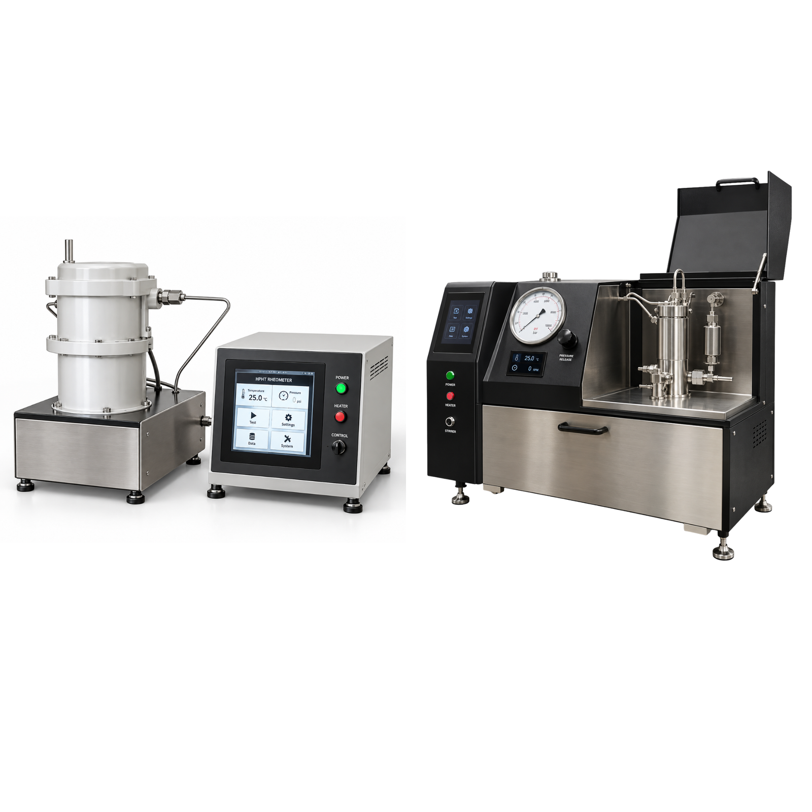
Figures 2a and 2b. Ultra HTHP Laboratory Rheometer (reference photographs). Components are listed on page 2.
Intended applications
• Rheological profiling of HTHP water-based and oil-based muds through temperature and pressure cycles.
• Gel-strength progression, thermal thinning and barite-sag risk in deep, hot wells.
• Testing completion brines, fracturing gels and viscosified spacers.
• Generating shear stress vs shear rate data for hydraulics software and model fitting.
FEATURES
• Programmable heating to 320 C with ramp, hold and cool-down profiles.
• Magnetic-drive coaxial geometry that avoids dynamic seal friction on the torque path.
• Automated shear-rate sweeps with software calculation of PV, YP, n and K.
• Pressure-relief and over-temperature protection.
• Data logging and export for QA records.
TECHNICAL SPECIFICATIONS
| Maximum Temperature | 320°C (608°F) as per equipment designation |
| Maximum Pressure | Typically 10,000–20,000 psi class (confirm on datasheet) |
| Geometry | Coaxial cylinder, API-equivalent shear-rate factor |
| Speed Range | Typically 1–600 rpm, programmable |
| Sample Volume | Typically 50–150 mL depending on cell |
| Heating / Control | Electric jacket, PID controlled |
| Data Interface | PC software with real-time plotting and export |
Main components (see Figure 2)
| No. | Component |
| 1 | Drive motor and magnetic coupling |
| 2 | Control cabinet with display |
| 3 | Pressure line and gauge |
| 4 | Heating jacket and pressure cell |
| 5 | Cooling coil and pressurising line |
| 6 | Base frame |
Principle of operation
Basic operating procedure
1. Prepare and condition the sample according to the test plan; record fluid density.
2. Fill the cell to the mark, fit the rotor and close the cell with the correct seals.
3. Pressurise with nitrogen to the initial pressure and check for leaks.
4. Program the temperature, pressure and shear-rate profile in the software.
5. Run the test and monitor torque, temperature and pressure in real time.
6. Cool below 50 C, vent pressure slowly, open the cell, remove the sample and clean all parts.
Calibration and maintenance
• Replace O-rings and seals on schedule; use high-temperature thread lubricant.
• Check torque calibration with a Newtonian oil at ambient temperature.
• Calibrate thermocouple and pressure transducer at least annually.
• Test the pressure-relief device and inspect vessel threads for wear.
Safety precautions
• Never open the cell above 50 C or while pressurised.
• Use a face shield and heat-resistant gloves; secure nitrogen cylinders.
• Operate only within the rated pressure and temperature; trained personnel only.
Reference sources
• API RP 13D, Rheology and Hydraulics of Oil-Well Drilling Fluids
• API RP 13B-1 / ISO 10414-1, Field Testing of Water-Based Drilling Fluids; API RP 13B-2 / ISO 10414-2, Field Testing of Oil-Based Drilling Fluids
• OFITE Model 1100 HTHP viscometer literature
• Chandler Engineering Model 7600 HPHT viscometer literature