
MUD TESTING EQUIPMENT
For years, Inmotion Energy has supplied
precision instruments and drilling tools for
testing drilling fluids, well cements, and
completion fluids.
From our Bangalore facility, we provide
customers across India and the Middle East
with quality products and exceptional
service.
INDUSTRIES WE SERVE
— Onshore & offshore drilling contractors
— National & independent oil companies
— Mud engineering & testing laboratories
— Well completion & workover operations
WHY CHOOSE US
— Rigorous quality control on every unit
— Fast turnaround on spares &
replacements
— Field-tested designs, built for uptime
INMOTION ENERGY (OPC) PRIVATE LIMITED
- 186, 1st Main Road, Vijaya Bank Layout, Bilekahalli, Bangalore, Karnataka – 560076
- Phone: +91 96637 44619
- info@inmotionenergy.in
- imotion.in
PRODUCT SPECIFICATION — Atmospheric Swell Meter (Single)
Model: IM-LSM-01 Compliance / target standard: Shale Hydration Modeling
Atmospheric Swell Meter (Single)
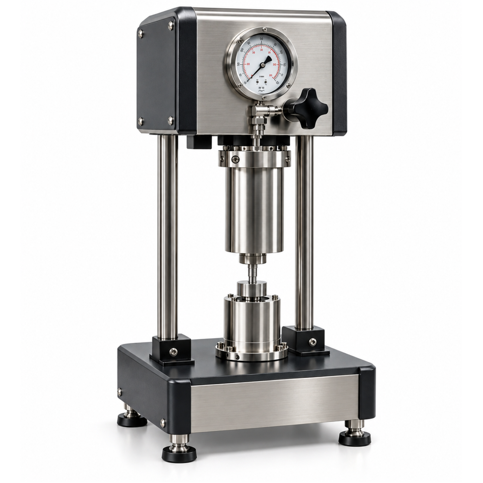
Figure 10. Reference photograph of the Atmospheric Swell Meter (Single). Components are listed on page 2.
Intended applications
• Ranking shale inhibitors such as KCl, polymers and amines by swelling reduction.
• Testing the reactivity of field cuttings or reconstituted clay wafers.
• Fluid optimisation for wellbore-stability programs.
• Comparing base fluids with new inhibition additives.
FEATURES
• LVDT displacement sensor with micron-level resolution.
• Perforated sample holder to expose the wafer to fluid on all sides.
• Open fluid cup with simple loading and cleaning.
• Digital readout with continuous time-based logging.
• Compact bench-top format.
TECHNICAL SPECIFICATIONS
| Sensor | LVDT displacement transducer |
| Sample | Compacted wafer, typically about 25 mm diameter x 6 mm thick |
| Test Conditions | Ambient temperature and atmospheric pressure |
| Test Duration | Typically 2-24 hours, per laboratory SOP |
| Measured Value | Linear swell, % = (change in height / initial height) x 100 |
| Resolution | Micron-level (confirm on datasheet) |
| Data Output | Readout with logging |
Main components (see Figure 1)
| No. | Component |
| 1 | LVDT displacement sensor |
| 2 | Core rod |
| 3 | Compacted sample wafer |
| 4 | Readout unit |
| 5 | Fluid cup |
| 6 | Stand base |
Principle of operation
Basic operating procedure
1. Grind and dry the shale sample and compact a wafer of fixed mass at the specified pressure and dwell time.
2. Place the wafer in the holder and position the holder in the empty cup.
3. Lower the LVDT rod onto the wafer and set the reading to zero.
4. Pour the test fluid into the cup to cover the wafer and start logging.
5. Record the swelling at fixed intervals until the curve levels off or the test time ends.
6. Remove the fluid, clean the parts, and calculate and report swell percentage against time.
Calibration and maintenance
• Check LVDT zero and linearity with reference gauge blocks.
• Keep the core rod straight and free of deposits; clean the holder screen.
• Keep cables and connectors dry.
• Verify the compaction procedure with reference clay.
Safety precautions
• Handle powdered clay with a dust mask.
• Wear gloves when using chemical inhibitors.
• Dispose of used fluids per site rules.
Reference sources
• US Patent 5,110,484 (example of LVDT swelling tests using compacted clay wafers)
• ISO/NP 26652, linear swelling ratio of shale using a dilatometer (under development)
• OFITE linear swell meter product literature