
MUD TESTING EQUIPMENT
For years, Inmotion Energy has supplied
precision instruments and drilling tools for
testing drilling fluids, well cements, and
completion fluids.
From our Bangalore facility, we provide
customers across India and the Middle East
with quality products and exceptional
service.
INDUSTRIES WE SERVE
— Onshore & offshore drilling contractors
— National & independent oil companies
— Mud engineering & testing laboratories
— Well completion & workover operations
WHY CHOOSE US
— Rigorous quality control on every unit
— Fast turnaround on spares &
replacements
— Field-tested designs, built for uptime
INMOTION ENERGY (OPC) PRIVATE LIMITED
- 186, 1st Main Road, Vijaya Bank Layout, Bilekahalli, Bangalore, Karnataka – 560076
- Phone: +91 96637 44619
- info@inmotionenergy.in
- imotion.in
PRODUCT SPECIFICATION — Permeability Plugging Tester (PPT)
Model: IM-PPA-189 Compliance / target standard: API RP 13B-1 Annex
Permeability Plugging Tester (PPT)
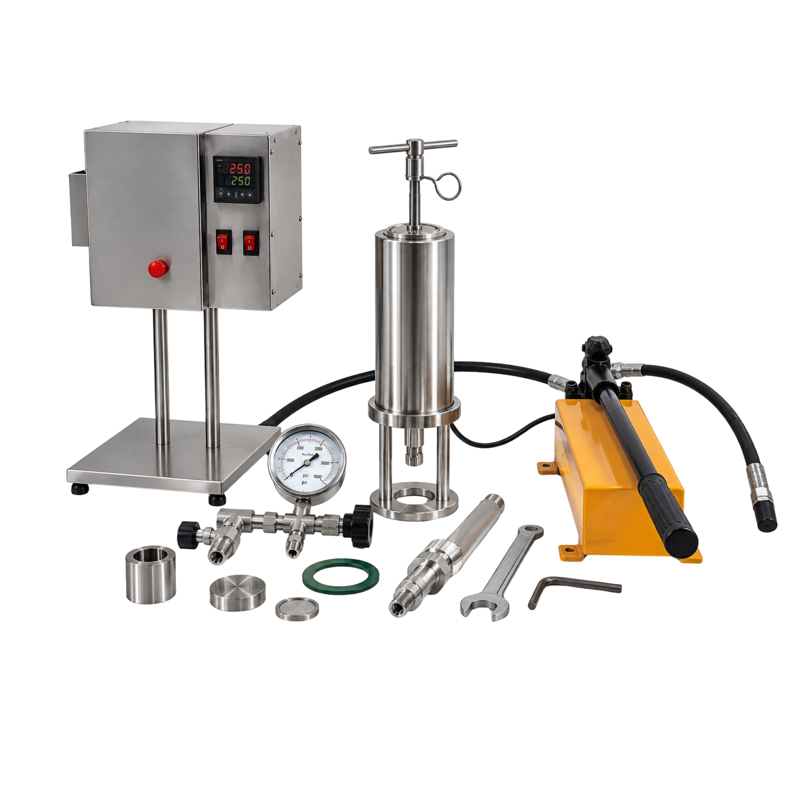
Figure 14. Reference photograph of the Permeability Plugging Tester (PPT) kit, with heating/control unit, cell, hydraulic hand pump and accessories. Components are listed on page 2.
Intended applications
• Assessing the ability of fluids and sizing of bridging agents to plug formation pores.
• Testing lost-circulation materials (LCM) and wellbore-strengthening blends.
• HTHP filtration control evaluation of muds.
• Selecting ceramic disk grades that represent reservoir permeability.
FEATURES
• Stainless steel cell rated to about 5,000 psi and 500 F (260 C) in the typical class.
• Ceramic disks of selectable pore-throat size and permeability.
• Heating jacket with thermometer.
• Back-pressure receiver rated to about 750 psi.
• Hydraulic hand pump and pressurising assembly.
TECHNICAL SPECIFICATIONS
| Maximum test pressure | About 5,000 psi (34,473 kPa) typical class |
| Maximum temperature | About 500 F (260 C) typical class |
| Back-pressure receiver | Up to about 750 psi (5,171 kPa) |
| Filter medium | Ceramic disk (various pore sizes) |
| Pressure supply | Hydraulic hand pump; CO2 / N2 back pressure |
| Measured values | Spurt loss and filtrate volume vs. time |
| Reporting | Filtrate volume corrected to API filter area (verify factor in manual) |
Main components (see Figure 1)
| No. | Component |
| 1 | Top valve and T-screws |
| 2 | Ceramic disk |
| 3 | Dial thermometer |
| 4 | Back-pressure receiver |
| 5 | Heating jacket and cell |
| 6 | Hydraulic hand pump |
Principle of operation
Basic operating procedure
1. Assemble the cell with the ceramic disk pre-saturated and fill with mud, allowing for expansion.
2. Close the cell and place it in the heating jacket; connect the back-pressure receiver and pump.
3. Apply the back pressure (for example 500 psi) and heat to the test temperature.
4. Apply the differential pressure with the hand pump and open the valve to start filtration.
5. Collect filtrate at set times (e.g. 1, 7.5, 15 and 30 minutes) and record spurt loss.
6. Cool below 50 C, vent, disassemble and record results; correct total filtrate to the API filter area if required.
Calibration and maintenance
• Inspect O-rings and threads and replace seals regularly.
• Check that disks are clean and undamaged; clean or replace after each test.
• Calibrate pressure gauge and thermometer annually.
• Test the relief device and hydraulic system.
Safety precautions
• High pressure and temperature: never open the cell hot or pressurised.
• Use a face shield and heat-resistant gloves; keep within rated limits.
• Ensure that the receiver is depressurised before disconnecting.
Reference sources
• API RP 13B-1 / ISO 10414-1, Field Testing of Water-Based Drilling Fluids (HTHP filtration and annex on PPT)
• OFITE Permeability Plugging Apparatus (PPA) literature
• US Patent application CA 2887847 (LCM testing within a PPA)
• Fann / Chandler HTHP filtration cell manuals