
MUD TESTING EQUIPMENT
For years, Inmotion Energy has supplied
precision instruments and drilling tools for
testing drilling fluids, well cements, and
completion fluids.
From our Bangalore facility, we provide
customers across India and the Middle East
with quality products and exceptional
service.
INDUSTRIES WE SERVE
— Onshore & offshore drilling contractors
— National & independent oil companies
— Mud engineering & testing laboratories
— Well completion & workover operations
WHY CHOOSE US
— Rigorous quality control on every unit
— Fast turnaround on spares &
replacements
— Field-tested designs, built for uptime
INMOTION ENERGY (OPC) PRIVATE LIMITED
- 186, 1st Main Road, Vijaya Bank Layout, Bilekahalli, Bangalore, Karnataka – 560076
- Phone: +91 96637 44619
- info@inmotionenergy.in
- imotion.in
PRODUCT SPECIFICATION — Six-Link LPLT Filtration Bench
Model: IM-MFP-LPLT6 Compliance / target standard: High-Throughput Commercial
Six-Link LPLT Filtration Bench
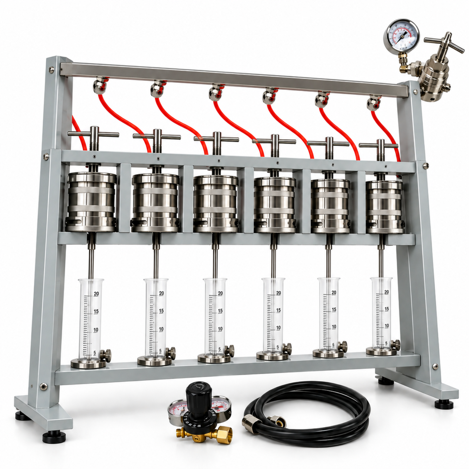
Figure 5. Reference photograph of the Six-Link LPLT Filtration Bench, with six filter cells, pressure manifold and regulator/hose set. Components are listed on page 2.
Intended applications
• High-volume filtration screening of additives and mud formulations.
• Quality control of incoming batches in commercial mud laboratories.
• Parallel comparison of six treatment levels of a fluid-loss additive.
• Time-efficient training and proficiency testing.
FEATURES
• Six cells tested simultaneously under identical pressure.
• Individual inlet valves and receivers for staggered starts.
• Bench-top frame with fixed positions for repeatable set-up.
• Common manifold and gauge for consistent 100 psi supply.
• Rugged construction for continuous laboratory use.
TECHNICAL SPECIFICATIONS
| Number of Cells | 6, tested simultaneously |
| Test Pressure | 100 +/- 5 psi (690 +/- 35 kPa) per cell |
| Filter Area (Each) | 7.1 in² (45.8 cm²), API standard |
| Test Duration | 30 minutes (per API) |
| Pressure Source | Regulated CO2 or nitrogen through common manifold |
| Filter Medium | 90 mm hardened filter paper |
| Receivers | 6 x 10 / 25 mL graduated cylinders |
Main components (see Figure 5)
| No. | Component |
| 1 | Individual cell inlet valve |
| 2 | Common pressure manifold |
| 3 | Regulator and gauge |
| 4 | Filter cell |
| 5 | Frame and base |
| 6 | Filtrate receiver |
Principle of operation
Basic operating procedure
1. Assemble six dry cells (screen, filter paper, gasket), fill with mud and close; label each cell.
2. Mount the cells in the frame and connect their inlet valves; ensure all valves are closed.
3. Place a dry graduated cylinder under each drain tube.
4. Set the regulator to 100 psi; open the valves one after another and start each timer.
5. At 30 minutes record each filtrate volume, close the valve and relieve pressure.
6. Remove the cells, measure cake thickness, and record all results against the labels.
Calibration and maintenance
• Leak-check the manifold and all six valves at working pressure.
• Replace O-rings, gaskets and screens on a fixed schedule.
• Calibrate the gauge periodically; keep a log of calibration.
• Clean cells and receivers after every run; store dry.
Safety precautions
• Relieve pressure from each cell before opening.
• Secure any gas cylinder used as pressure source.
• Wear eye protection and gloves; keep the bench area clear.
Reference sources
• API RP 13B-1 / ISO 10414-1, Field Testing of Water-Based Drilling Fluids (filtration section)
• OFITE multiple-unit low-pressure filter press literature
• Fann multi-unit filter press manuals
• ISO 10414-1:2008